|
|
|
|
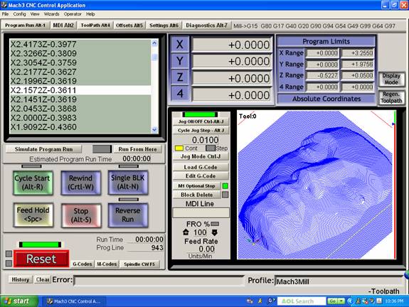
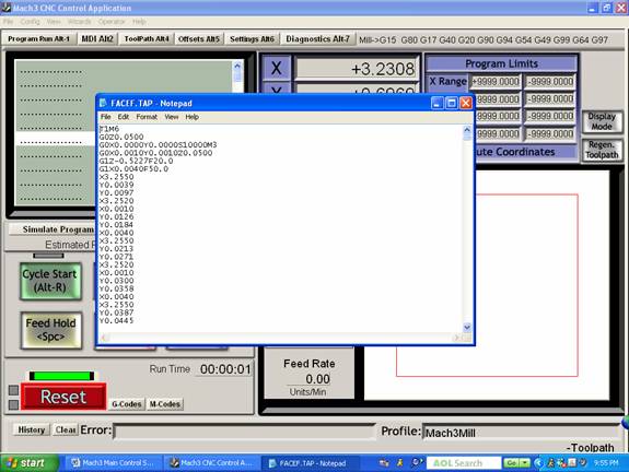
Custom Mach 3 Software Control InterfaceThe Mach 3 control software provides a powerful Windows interface to the MicroMill DSLS 3000 or 2000 system. A screen shot of the main custom control window is shown below.
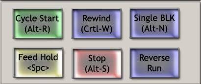
Main Program Control Buttons
Cycle StartThis executes the current G-code program when pressed. The shortcut keys are Alt-R.RewindThis rewinds the current G-code program back to the beginning. The shortcut keys are Ctrl-W.Single BLKThis activates single line program operation. When pressed the yellow indicator light above the button will flash to indicate it is active. When the Cycle Start button is pressed only a single line of G-code will be executed. The shortcut keys are Alt-N.StopThis immediately stops the program or machine movement. The shortcut keys are Alt-S.Feed HoldThis stops the program after a movement ramp down has finished. The shortcut key is the Spacebar.Reverse RunThis allows the G-code program to be run in the reverse direction.
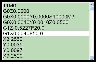
G-Code Program Display
The G-code program display shows 10 program lines of code. The current line of code that is being executed is highlighted in white. The previous 5 lines of code and the next 4 lines of code are shown so the user can easily follow the program progress. When the G-code program is stopped the user can click in the display box causing the entire box to become bright. From this point the user can scroll through the program code with the slide bar or mouse wheel.
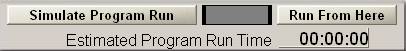
Simulate Program Run and Run From Here
The Simulate Program Run button allows the user to quickly execute the program without any machine movement to get an estimated program run time. This time is then displayed. It is worth noting that this doesn’t give a very precise time estimate in many cases since it doesn’t account for axis acceleration and deceleration which may add up to a significant amount of time if you have a program with many short movement segments.The Run From Here button allows the user to highlight a line of code in the program from which to start the program when the Cycle Start button is pushed. The user simply scrolls down through the program until the desired line is highlighted in white. When the desired starting line is highlighted press the Run From Here button and the program lines will be quickly scrolled through until that line of code is reached. The user then simply presses Cycle Start to execute the program from that line.
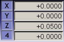
Machine Tool Coordinates
This displays the current X, Y, Z, and 4th axis coordinates of the machine tool. The display is updated dynamically as the machine movement occurs. The instantaneous machine position is, therefore, displayed at all times. The coordinate of any axis can be changed by clicking in its box and highlighting it in white. Any number value can then be typed in to change it. The Enter key must be pressed at the end to change it to the new number.
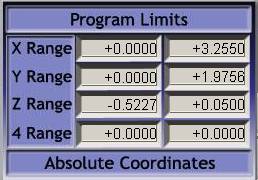
Program Limits
The program limits display shows the minimum and maximum values for each axis that a part program will move to when executed. It is immediately displayed after the G-code program is loaded.
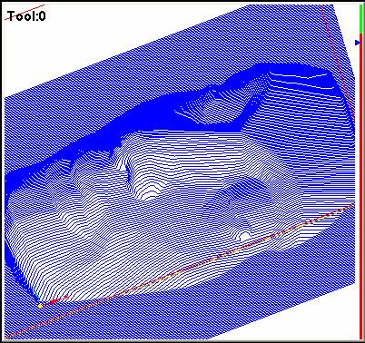
3D Graphic Part Display
The graphic display shows the complete part geometry. The perspective view can be manipulated by clicking on the part with the left mouse button and rotating it with the mouse. The right mouse button allows the user to translate the part view in the window while the mouse wheel allows zooming in and out. A double mouse click resets the view back to a 2D plane view directly down on the part. During program execution the toolpath is drawn over the part geometry as a green line.
Graphic Display Buttons
The Display Mode button changes between different graphic display views. Pressing it toggles between the part limit view and machine limit view.Regen. Toolpath is pressed to redraw the part program to refresh it or when the coordinates are changed to reposition the toolpath display.
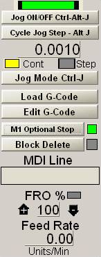
Custom Machine Control Section
Jog ON/OFFThis activates manual jogging of the machine tool via the keyboard. If manual jogging is activated the indicator above the button will be green. The shortcut keys are Ctrl-Alt-J.Cycle Jog StepPressing this button cycles through the 10 preset jog increments that are defined in the Config – State section. The user can also click in the number display box and enter any desired jog increment number. Each axis will move this jog increment value when its jog key is pressed and the Jog Mode (see next) is set to Step. The shortcut keys are Alt-J.Jog ModeThis toggles between Continuous and Step Jog Mode as indicated by which indicator light is yellow. In Continuous Jog mode the machine axis is moved at Rapid Speed as long as the axis jog key is pressed. In Step mode the machine axis is moved the jog step distance set with the Cycle Jog Step button. The shortcut keys are Ctrl-J.Load G-CodeThis opens up the standard Open File window that allows a G-code program to be loaded.Edit G-codeThe Edit G-code selection button launches the standard Windows Notepad program displaying the current program loaded as shown below. The user can then edit the G-code program just like a standard Notepad text document. Saving the file immediately changes the currently loaded program upon exit from Notepad. The modified program can then be executed as normal. The program can also be saved as another file name with the standard Save As option, in which case the current program is not modified.
M1 Optional StopThis activates the M1 optional stop function in a G-code program. When activated the indicator light will be green and all M1 codes in a program will stop the program at that line.Block DeleteActivates the standard block delete in a G-code program. The indicator light will be green when activated. When activated any line starting with a slash \ will not be executed when the program is run.MDI Line
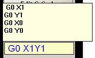
This is the Manual Data Input (MDI) line that allows the user to type in a short line of G-code. When the user clicks in the box it is highlighted yellow showing the cursor and also displays a small window showing the last 4 lines of code entered as shown above. A single line of G-code can then be entered. This G-code line is immediately executed upon hitting the Enter key. Note: If you need to type in a line of code that exceeds the length of the given box then you must go to the MDI Screen for this.FRO %This is the Feed Rate Override that displays the percent value used to scale the current Feed rate in the G-code program. The value is increased using the plus arrow to the left of the display while the negative arrow to the right of the display decreases it. The value can also be changed by clicking directly in the display box and Entering a new value. A value of 100 allows the Feed rates to be used as programmed. Any value other than 100 turns the indicator light yellow to show that the Feed rate is being scaled by the percentage value shown.Feed RateThis shows the instantaneous Feed Rate that the axes are moving at. It is a true vector value of the dynamic machine movement velocity. The rate is indicated in Units per Minute. The Units can be in mm or INCH.
|
Send mail to sales@microproto.com
with questions or comments about this web site.
|